As you may have noticed by looking at my other works, I’m a computer guy, not an electronics designer.
But due to the lack of a good FPGA designer / PCB designer in Iran, the only way for me to develop my AI software on some real robots, was to design the electronics myself!
Its main responsibilities, is to receive commands from the main computer through wireless link, drive the robots’ motors, apply a control loop on the motors, do some local sensing and send some feedback data to the main computer. Also it had to be fitted into a maximum size of 10*9 cm!
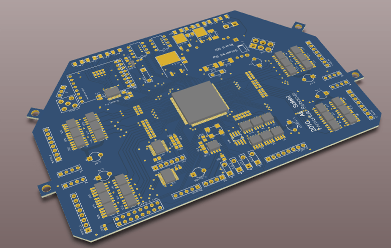
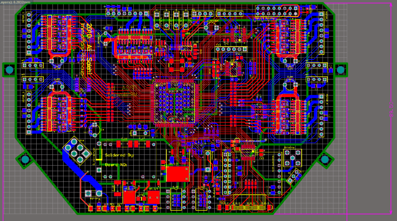
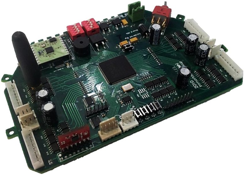
So here’s the result:
- A Xilinx FPGA containing 400,000 logic gates as the main processor.
- 2.4 GHz full duplex wireless communication, with a total bandwidth of 2Mbps. It uses my own software layer, which allows 12-bit addressing (much more than the requirements for our purpose), delivery acknowledging and auto re-transmitting when required, auto detection of the working channel, signal strength detection and much more.
- An alternative 915 MHz RF communication, with much lower bandwidth (38 Kbps), to use when the ISM band traffic is too high, or a higher range is needed.
- TSK3000A, a 32-bit RISC soft-processor, implemented inside the FPGA. It has 5 pipelines, and a theoretical value of 1.2 MIPS per MHz. We use this processor at the frequency of 40 MHz. It’s the main processing unit of the board.
- 9-Axis IMU, used to determine a local transformation of the robot. This local data are used when:
- There are lost packets
- The vision could not determine the global state
- Removing the global vision latency by predicting the vision data (for about 150 mS)
- BLDC motor drivers, capable of driving 5 BLDC motors at a very high frequency, using hall-sensor commutation. The commutation logic is implemented inside the FPGA.
- A flash memory, to save the firmware, its parameters’ values and debugging data. The firmware allows the downloading of a newer version, changing the parameters, and error reading via the wireless link.
From an electrical point of view, the PCB is designed in a multi-layer fashion (4-layer). This is because of the FPGA requirements, and the very high current drawn by the BLDC motors (230 amperes!).
There are 500+ electrical components used in this PCB. Dividing the component count by the PCB area (10*9 cm) gives us the component density of about 6 components per square cm!

There are 6 voltage rails needed by the components, including: 1.2V, 2.5V, 3.3V, 5.0V, 7.5V and 14V.
The main battery voltage is 14.8V. The PSU includes a switching regulator that converts the battery voltage to 5.0V. Then 3 LDO regulators are used for providing lower voltages.
One of the four layers of the PCB is used solely for feeding all the the VCCs into the components, and one is just the holy GND!

The firmware of the FPGA is developed using Altium Designer. It allows developing both logic design and embedded software for the soft processor in one tool. The embedded software is written in C, and the logic design is done using a combination of schematics, Verilog and VHDL.
Features that require parallelism and least delay are implemented in logic, including:
- Rotary encoder sensor reading
- Voltage booster control signal generation
- BLDC commutation
- Timing of power mosfets’ switching to avoid short circuit
- An alternative simplified control loop for motors, based solely on hall sensors, used when rotary encoder data is somehow unavailable. These situations include:
- There was an error reading the encoder
- The encoder is not installed mechanically, on electronically, so they’re disabled by the user
The following features are implemented inside the TSK3000 processor:
- An error detection system, similar to the ones used in modern cars’ ECUs. It detects many errors, including low-voltage situations, voltage spikes, short circuits, over-temperature, daughter boards’ malfunction, packet drops, sensor reading errors, motor stuck situations and much more. Then these errors are written to the flash memory for later diagnostics. But some of them are categorized as critical, and the processor halts the function of the malfunctioned part, and report the situation by making an error-specific sound, turning the STOP led on, and sending it over to the main computer.
These errors should be cleared by using the diagnostics software, and the person erasing it should solve the problem before clearing it. - Acting as an odometer, calculating the usage of each part, including BLDC motors, voltage booster unit, servo motor, rotary encoders and the wheels. These data then are used by the rest of the team, to know when to change or check each unit.
- Providing real-time diagnostics data over wireless link, such as each motor speed, voltages of some critical points, state of debugging switches (believe it or not, they are the mother of many other malfunctions!), IMU data and voltage booster state.
- PID control loop with torque converter for each motor. The control loop frequency is 1.2 kHz, and delay time is 122 uS. The loop is so time-critical, and so is written in pure assembly.
